Bộ chuyển tín nhiệt độ 644RANAQ4
Thông số kỹ thuật Rosemount 644RANAQ4
- 644-Temperature Transmitter
- R-Transmitter type : Rail Mount – Single Sensor Input
- A-Output : 4–20 mA with digital signal based on HART protocol (Head & Rail)
- NA-Product certifications-Hazardous Locations Certificates (consult factory for availability) No approval
- Q4-Calibration certificate -Calibration certificate. 3-Point calibration with certificate
- Weight : 174 g
- Shipping Weight: 0.5 kg
- đại lý 644RANAQ4 | nhà phân phối 644RANAQ4
| Model | 644 | Temperature Transmitter |
| Transmitter type | R | Rail Mount – Single Sensor Input |
| Output | A | 4–20 mA with digital signal based on HART protocol |
| Product certifications | NA | No approval |
| Calibration certificate | Q4 | 5-point calibration (use option code Q4 to generate a calibration certificate) |
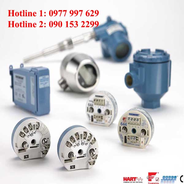
Rosemount 644 là Máy phát nhiệt độ đa năng mang lại độ tin cậy tại hiện trường cũng như độ chính xác và ổn định nâng cao để đáp ứng các nhu cầu khắt khe của quy trình.
Các tính năng của máy phát bao gồm:
- HART/4-20 mA with Selectable Revision 5 and 7 selectable (Option Code A), Foundation fieldbus (Option Code F) or PROFIBUS PA (Option Code W)
- DIN A Head Mount, Field Mount, or Rail Mount transmitter styles
- Dual Sensor Input (Option Code S)
- SIS SIL 2 Safety Certification (Option Code QT)
- LCD Display (Option Code M5)
- Local Operator Interface (Option Code M4)
- Advanced Diagnostics (Option Codes DC and DA1)
- Enhanced Transmitter Accuracy and Stability
(Option Code P8)
- Transmitter-Sensor Matching (Option Code C2)
Specification and selection of product materials, options, or components must be made by the purchaser of the equipment. See page 14 for more information on Material Selection.
Table 1. Rosemount 644 Smart Temperature Transmitter Ordering Information
★ The Standard offering represents the most common models and options. These options should be selected for best delivery.
The Expanded offering is manufactured after receipt of order and is subject to additional delivery lead time.
- = Available
– = Not Available
| Model | Product description | |||||
| 644 | Temperature Transmitter | |||||
| Transmitter type | ||||||
| H | DIN A Head Mount – Single Sensor Input | ★ | ||||
| R | Rail Mount – Single Sensor Input | ★ | ||||
| S | DIN A Head Mount – Dual Sensor Input (HART only) | ★ | ||||
| F(1) | Field Mount – Single Sensor Input (HART only) | ★ | ||||
| D<1) | Field Mount – Dual Sensor Input (HART only) | ★ | ||||
| Output | Head | Rail | ||||
| A | 4-20 mA with digital signal based on HART protocol | • | • | ★ | ||
| F | Foundation fieldbus digital signal (includes 2 AI function blocks and Backup Link Active Scheduler) | • | – | ★ | ||
| W | PROFIBUS PA digital signal | • | – | ★ | ||
| Product certifications | Head | Rail | ||||
| Hazardous locations certificates (consult factory for availability^2)) | A | F | W | A | ||
| NA | No approval | • | • | • | • | ★ |
| E5 | FM Explosion-proof; Dust Ignition-proof | • | • | • | – | ★ |
Table 1. Rosemount 644 Smart Temperature Transmitter Ordering Information
★ The Standard offering represents the most common models and options. These options should be selected for best delivery. The Expanded offering is manufactured after receipt of order and is subject to additional delivery lead time.
- = Available
– = Not Available
| Head | Rail | |||||
| A | F | W | A | |||
| I5 | FM Intrinsically Safe; Non-incendive | • | • | • | • | ★ |
| K5 | FM Explosionproof; Intrinsically Safe; Non-incendive; Dust Ignition-proof | • | • | • | – | ★ |
| NK | IECEx Dust | • | – | – | – | ★ |
| KC | FM and CSA Intrinsically Safe and Non-incendive | – | – | – | • | ★ |
| KB | FM and CSA: Explosionproof; Intrinsically Safe; Non-incendive; Dust Ignition-proof | • | – | – | – | ★ |
| KD | FM, CSA and ATEX Explosionproof, Intrinsically Safe | • | • | • | ★ | |
| I6 | CSA Intrinsically Safe | • | • | • | • | ★ |
| K6 | CSA Explosionproof; Intrinsically Safe; Non-incendive; Dust Ignition-proof | • | • | • | – | ★ |
| I3 | China Intrinsic Safety | • | – | – | – | ★ |
| E3 | China Flameproof | • | • | • | – | ★ |
| N3 | Chine Type n | • | – | – | – | ★ |
| E1 | ATEX Flameproof | • | • | • | – | ★ |
| N1 | ATEX Type n | • | • | • | – | ★ |
| NC | ATEX Type n Component | • | • | • | • | ★ |
| K1 | ATEX Flameproof; Intrinsic Safety; Type n; Dust | • | • | • | ★ | |
| ND | ATEX Dust Ignition-Proof | • | • | • | – | ★ |
| KA | CSA and ATEX: Explosionproof; Intrinsically Safe; Non-incendive | • | – | – | – | ★ |
| I1 | ATEX Intrinsic Safety | • | • | • | • | ★ |
| E7 | IECEx Flameproof | • | • | • | – | ★ |
| I7 | IECEx Intrinsic Safety | • | • | • | • | ★ |
| N7 | IECEx Type n | • | • | • | – | ★ |
| NG | IECEx Type n Component | • | • | • | • | ★ |
| K7 | IECEx Flameproof; Intrinsic Safety; Type n; Dust | • | – | – | – | ★ |
| I2 | INMETRO Intrinsic Safety | • | – | – | – | ★ |
| E4 | TIIS Flameproof | • | • | – | – | ★ |
| E2 | INMETRO Flameproof | • | • | • | – | ★ |
| EM | Technical Regulations Customs Union (EAC) Flameproof | • | • | • | – | ★ |
| IM | Technical Regulations Customs Union (EAC) Intrinsic Safety | • | • | • | – | ★ |
| KM | Technical Regulations Customs Union (EAC) Flameproof, Intrinsic Safety | • | • | • | – | ★ |
Options
| Head | Rail | ||||
| A | F | W | A | ||
| PlantWeb standard diagnostic functionality | |||||
| DC Diagnostics: Hot Backup and Sensor Drift Alert | • | – | – | – | ★ |
Table 1. Rosemount 644 Smart Temperature Transmitter Ordering Information
★ The Standard offering represents the most common models and options. These options should be selected for best delivery. The Expanded offering is manufactured after receipt of order and is subject to additional delivery lead time.
- = Available
– = Not Available
| PlantWeb advanced diagnostic functionality | |||||||||
| DA1 | HART Sensor and Process Diagnostic Suite: Thermocouple Diagnostic and Min/Max Tracking | • | – | – | – | ★ | |||
| Enclosure options | Head | Rail | |||||||
| A | F | W | A | ||||||
| Housing style | Material | Entry size | Diameter | ||||||
| J5(3)(4) | Universal Junction Box, 2 entries | Aluminum | M20 X 1.5 | 3 in (76 mm) | • | • | • | – | ★ |
| J6(4) | Universal Junction Box, 2 entries | Aluminum | 1/2-14 NPT | 3 in (76 mm) | • | • | • | – | ★ |
| R1 | Rosemount Connection Head, 2 entries | Aluminum | M20 X 1.5 | 3 in (76 mm) | • | • | • | – | ★ |
| R2 | Rosemount Connection Head, 2 entries | Aluminum | 1/2-14 NPT | 3 in (76 mm) | • | • | • | – | ★ |
| J1(3) | Universal Junction Box, 3 entries | Aluminum | M20 X 1.5 | 3.5 in (89 mm) | • | • | • | – | ★ |
| J2 | Universal Junction Box, 3 entries | Aluminum | 1/2-14 NPT | 3.5 in (89 mm) | • | • | • | – | ★ |
| D1(1)(3)(5) | Field Mount Housing, Separate Terminal Compartment | Aluminum | M20 X 1.5 | 3.5 in (89 mm) | – | – | – | – | ★ |
| D2( | Field Mount Housing, Separate Terminal Compartment | Aluminum | 1/2-14 NPT | 3.5 in (89 mm) | – | – | – | – | ★ |
| J3(3) | Universal Junction Box, 3 entries | Cast SST | M20 X 1.5 | 3.5 in (89 mm) | • | • | • | – | |
| J4 | Universal Junction Box, 3 entries | Cast SST | 1/2-14 NPT | 3.5 in (89 mm) | • | • | • | – | |
| J7(3)(4) | Universal Junction Box, 2 entries | Cast SST | M20 X 1.5 | 3 in (76 mm) | • | • | • | – | |
| J8(4) | Universal Junction Box, 2 entries | Cast SST | 1/2-14 NPT | 3 in (76 mm) | • | • | • | – | |
| R3 | Rosemount Connection Head, 2 entries | Cast SST | M20 X 1.5 | 3 in (76 mm) | • | • | • | – | |
| R4 | Rosemount Connection Head, 2 entries | Cast SST | 1/2-14 NPT | 3 in (76 mm) | • | • | • | – | |
| S1 | Connection Head, 2 entries | Polished SST | 1/2-14 NPT | 3 in (76 mm) | • | • | • | – | |
| S2 | Connection Head, 2 entries | Polished SST | 1/2-14 NPSM | 3 in (76 mm) | • | • | • | – | |
| S3 | Connection Head, 2 entries | Polished SST | M20 X 1.5 | 3 in (76 mm) | • | • | • | – | |
| S4 | Connection Head, 2 entries | Polished SST | M20 X 1.5,
M24 X 1.4 |
3 in (76 mm) | • | • | • | – | |
| Mounting bracket | |||||||||
| B4(6) | 316 SST U-bolt Mounting Bracket, 2-in pipe mount | • | • | • | – | ★ | |||
| B5(6) | “L” Mounting Bracket for 2-inch pipe or panel mounting | • | • | • | – | ★ | |||
| Display and interface options | |||||||||
| M4 | LCD Display with Local Operator Interface | • | – | – | – | ★ | |||
| M5 | LCD Display | • | • | • | – | ★ | |||
| Software configuration | |||||||||
| C1 | Custom Configuration of Date, Descriptor and Message (requires CDS with order) | • | • | • | • | ★ | |||
| Enhanced performance | |||||||||
| P8(7) | Enhanced Transmitter Accuracy and Stability | • | – | – | – | ★ | |||
Table 1. Rosemount 644 Smart Temperature Transmitter Ordering Information
★ The Standard offering represents the most common models and options. These options should be selected for best delivery. The Expanded offering is manufactured after receipt of order and is subject to additional delivery lead time.
- = Available
– = Not Available
| Alarm level configuration | ||||||
| A1 | NAMUR alarm and saturation levels, high alarm | • | – | – | • | ★ |
| CN | NAMUR alarm and saturation levels, low alarm | • | – | – | • | ★ |
| C8 | Low Alarm (Standard Rosemount Alarm and Saturation Values) | • | – | – | • | ★ |
| Line filter | Head | Rail | ||||
| F5 | 50 Hz Line Voltage Filter | • | • | • | • | ★ |
| F6 | 60 Hz Line Voltage Filter | • | • | • | • | ★ |
| Sensor trim | ||||||
| A | F | W | A | |||
| C2 | Transmitter-Sensor Matching – Trim to Specific Rosemount RTD Calibration Schedule (CVD constants) | • | • | • | • | ★ |
| 5-point calibration option | ||||||
| C4 | 5-point calibration (use option code Q4 to generate a calibration certificate) | • | • | • | • | ★ |
| Calibration certificate | ||||||
| Q4 | Calibration certificate (3-Point calibration with certificate) | • | • | • | • | ★ |
| QP | Calibration Certification & Tamper Evident Seal | • | • | • | – | ★ |
| Quality certification for safety | ||||||
| QT | Safety Certified to IEC 61508 with certificate of FMEDA data | • | – | – | – | ★ |
| Shipboard certification | ||||||
| SBS | American Bureau of Shipping (ABS) Type Approval | • | • | • | – | ★ |
| SBV | Bureau Veritas (BV) Type Approval | • | • | • | – | ★ |
| SDN | Det Norske Veritas (DNV) Type Approval | • | • | • | – | ★ |
| SLL | Lloyd’s Register (LR) Type Approval | • | • | • | – | ★ |
| External ground | ||||||
| G1 | External ground lug assembly (see “External ground screw assembly” on page 11) | • | • | • | – | ★ |
| Transient protection | ||||||
| T1(8) | Integral Transient Protector | • | – | – | – | ★ |
| Cable gland option | ||||||
| G2 | Cable gland (7.5 mm – 11.99 mm) | • | • | • | – | ★ |
| G7 | Cable gland, M20x1.5, Ex e, Blue Polyamide (5 mm – 9 mm) | • | • | • | – | ★ |
| Cover chain option | ||||||
| G3 | Cover chain | • | • | • | – | ★ |
| Conduit electrical connector | ||||||
| GE(9) | M12, 4-pin, Male Connector (eurofast®) | • | • | • | – | ★ |
| gm(9) | A size Mini, 4-pin, Male Connector (minifast®) | • | • | • | – | ★ |
Table 1. Rosemount 644 Smart Temperature Transmitter Ordering Information
★ The Standard offering represents the most common models and options. These options should be selected for best delivery. The Expanded offering is manufactured after receipt of order and is subject to additional delivery lead time.
- = Available
– = Not Available
| External label | ||||||
| EL | External label for ATEX Intrinsic Safety | • | • | • | – | ★ |
| HART revision configuration | Head | Rail | ||||
| A | F | W | A | |||
| HR5 | Configured for HART Revision 5 | • | – | – | – | ★ |
| HR7(10) | Configured for HART Revision 7 | • | – | – | – | ★ |
| Assemble to options | ||||||
| XA | Sensor Specified Separately and Assembled to Transmitter | • | • | • | – | ★ |
| Extended product warranty | ||||||
| WR3 | 3-year limited warranty | • | • | • | • | ★ |
| WR5 | 5-year limited warranty | • | • | • | • | ★ |
| Typical rail mount model number: 644 R A I5
Typical head mount model number: 644 S A I5 DC DA1J5 M5 Typical field mount model number: 644 F A I5 DC DA1 D1 M4 T1 |
||||||
| Consult factory on availability.
See Table 2 for the validity of enclosures with individual approval options. When ordered with XA, 72-in. NPT enclosure will come equipped With an M20 adapter with the sensor installed as a process ready. Enclosure ships equipped with 50.8 mm (2-in) SST pipe “U” bolt mounting kit. Available with Transmitter Type 644F or 644D only. Bracket assembly only available with J1, J2, J3, J4, D1, and D2. See Table 10 for Enhanced Accuracy specifications. Transient Protection option requires the use of J1, J2, J3, J4, D1, or D2. Available with Intrinsically Safe approvals only. For FM Intrinsically Safe or non-incendive approval (option code I5), install in accordance with Rosemount drawing 03151-1009. |
(10) Configures the HART output to HART Revision 7. The device can be field configured to HART Revision 5 if needed.
Note
For additional options (e.g. “K” codes), contact your local Emerson Process Management representative.
Table 2. 644 Enclosure Options Valid with Individual Approval Codes
| Code | Hazardous location approval description | Enclosure options valid with approval |
| NA | No approval | J1, J2, J3, J4, R1, R2, R3, R4, J5, J6, J7, J8, S1, S2, S3, S4, D1, D2 |
| E5 | FM Explosionproof; Dust Ignition-proof | J1. J2. J3. J4. R1, R2, R3,R4,J5. J6. J7. J8. D1, D2 |
| I5 | FM Intrinsically Safe; Non-incendive | J1. J2. J3. J4. R1, R2, R3, R4, J5. J6. J7. J8. D1, D2 |
| K5 | FM Explosionproof; Intrinsically Safe; Non-incendive; Dust Ignition-proof | J1. J2. J3. J4, R1. R2. R3, R4. J5. J6. J7. J8. D1. D2 |
| NK | IECEx Dust | J1. J2. J3. J4, R1. R2. R3, R4. J5. J6. J7. J8. D1. D2 |
| KC | FM and CSA Intrinsically Safe and Non-incendive | Only available with Rail mount device |
| KB | FM and CSA: Explosionproof; Intrinsically Safe; Non-incendive; Dust Ignition-proof | J2. J4, R2. R4, J6. J8. D2 |
| KD | FM, CSA and ATEX Explosionproof, Intrinsically Safe | J2. J4. R2. R4. J6. J8. D2 |
| I6 | CSA Intrinsically Safe | J1. J2. J3. J4. R1, R2. R3, R4, J5. J6. J7. J8. D1. D2 |
| K6 | CSA Explosionproof; Intrinsically Safe; Non-incendive; Dust Ignition-proof | J2. J4. R2. R4. J6. J8. D2 |
| I3 | China Intrinsic Safety | J1. J2. J3. J4. R1. R2. R3. R4. J5. J6. J7. J8 |
| E3 | China Flameproof | R1. R2. r3, R4. J5. J6. J7. J8 |
| N3 | China Type n | R1. R2. R3. R4, J5. J6. J7. J8 |
| E1 | ATEX Flameproof | J1. J2. J3. J4. R1. r2, R3, R4. J5. J6. J7. J8. D1. D2 |
| N1 | ATEX Type n | J1. J2. J3. J4. R1. R2. R3. R4. J5. J6. J7. J8. D1, D2 |
| NC | ATEX Type n Component | None |
| K1 | ATEX Flameproof; Intrinsic Safety; Type n; Dust | J1. J2. J3. J4. R1, R2, R3, R4, J5. J6. J7. J8. D1. D2 |
| ND | ATEX Dust Ignition-Proof | J1. J2. J3. J4. R1. R2. R3. R4. J5. J6. J7. J8. D1, D2 |
| KA | CSA and ATEX: Explosionproof; Intrinsically Safe; Non-incendive | J2. J4. R2. R4. J6. J8. D2 |
| I1 | ATEX Intrinsic Safety | J1. J2. J3. J4. R1. R2. R3. R4. J5. J6. J7. J8. S1. S2. S3. S4. D1. D2 |
| E7 | IECEx Flameproof | J1. J2. J3. J4. R1, R2, R3, R4, J5, J6, J7, J8, D1, D2 |
| I7 | IECEx Intrinsic Safety | J1, J2, J3, J4, R1, R2, R3, R4, J5, J6, J7, J8, S1. S2. S3. S4, D1. D2 |
| N7 | IECEx Type n | J1, J2, J3, J4, R1, R2, R3, R4, J5, J6, J7, J8, D1, D2 |
| NG | IECEx Type n Component | None |
| K7 | IECEx Flameproof; Intrinsic Safety; Type n; Dust | J1. J2. J3. J4, R1. R2. R3. R4. J5. J6, J7. J8, D1, D2 |
| I2 | INMETRO Intrinsic Safety | J1, J2, J3, J4, R1, R2, R3, R4, J5, J6, J7, J8 |
| E4 | TIIS Flameproof | J2, J6 |
| E2 | INMETRO Flameproof | R1. R2. R3. R4. J5. J6, J7. J8 |
| KM | Technical Regulations Customs Union (EAC) Flameproof, Intrinsic Safety | J1. J2. J3. J4.J5.J6, J7. J8, R1. R2. R3, R4. S1. S2. S3. S4 |
| IM | Technical Regulations Customs Union (EAC) Intrinsic Safety | J1. J2. J3. J4.J5.J6, J7. J8, R1. R2. R3, R4. S1. S2. S3. S4 |
| EM | Technical Regulations Customs Union (EAC) Flameproof | J1. J2. J3. J4.J5.J6, J7. J8. R1. R2. R3. R4. S1. S2. S3. S4 |
| K2 | INMETRO Flameproof, Intrinsic Safety | R1. R2. R3. R4. J5. J6. J7. J8 |
Tagging
Hardware
- 13 characters total
- Tags are adhesive or metal labels
- Tag is permanently attached to transmitter
Software
■ The transmitter can store up to 13 characters for Foundation fieldbus and PROFIBUS PA or 8 for HART protocol. If no characters are specified, the first 8 characters of the hardware tag are the default. An optional 32 character Long Software Tag is available when option code HR7 is ordered.
Considerations
External ground screw assembly
The external ground screw assembly can be ordered by specifying code G1 when an enclosure is specified. However, some approvals include the ground screw assembly in the transmitter shipment, hence it is not necessary to order code G1. The table below identifies which approval options include the external ground screw assembly and which do not.
| Option code | External ground screw assembly included? |
| E5, I1, I2, I5, I6, I7, K5, K6, NA, I3, KB | No-Order option code G1 |
| E1, E2, E3, E4, E7, K7, N1, N7, ND, K1, K2, KA, NK, N3, KD, T1 | Yes |
Table 3. Enclosure Spares
| Description | Part number |
| Universal Head, Aluminum, Standard cover, 2-conduit – M20 entries | 00644-4420-0002 |
| Universal Head, Aluminum, Display cover, 2-conduit – M20 entries | 00644-4420-0102 |
| Universal Head, Aluminum, Standard cover, 2-conduit – 1/2 – 14 NPT entries | 00644-4420-0001 |
| Universal Head, Aluminum, Display cover, 2-conduit – 1/2 – 14 NPT entries | 00644-4420-0101 |
| Universal Head, SST, Standard cover, 2-conduit – M20 entries | 00644-4433-0002 |
| Universal Head, SST, Display cover, 2-conduit – M20 entries | 00644-4433-0102 |
| Universal Head, SST, Standard cover, 2-conduit – 1/2 – 14 NPT entries | 00644-4433-0001 |
| Universal Head, SST, Display cover, 2-conduit – 1/2 – 14 NPT entries | 00644-4433-0101 |
| Connection Head, Aluminum, Standard cover, 2-conduit – M20 x 1/2 ANPT entries | 00644-4410-0021 |
| Connection Head, Aluminum, Display cover, 2-conduit – M20 x 1/2 ANPT entries | 00644-4410-0121 |
| Connection Head, Aluminum, Standard cover, 2-conduit – 1/2 – 14 NPT x 1/2 ANPT entries | 00644-4410-0011 |
| Connection Head, Aluminum, Display cover, 2-conduit – 1/2 – 14 NPT x 1/2 ANPT entries | 00644-4410-0111 |
| Connection Head, SST, Standard cover, 2-conduit – M20 X 1/2 ANPT entries | 00644-4411-0021 |
| Connection Head, SST, Display cover, 2-conduit – M20 X 1/2 ANPT entries | 00644-4411-0121 |
| Connection Head, SST, Standard cover, 2-conduit – 1/2 – 14 NPT x 1/2 ANPT entries | 00644-4411-0011 |
| Connection Head, SST, Display cover, 2-conduit – 1/2 – 14 NPT x 1/2 ANPT entries | 00644-4411-0111 |
| Connection Head, Polished SST, Standard cover, 2-conduit – M20 x 1.5 entries | 00079-0312-0033 |
| Connection Head, Polished SST, Display cover, 2-conduit – M20 x 1.5 entries | 00079-0312-0133 |
| Connection Head, Polished SST, Standard cover, 2-conduit – M20 x 1.5 / M24 x 1.5 entries | 00079-0312-0034 |
| Connection Head, Polished SST, Display cover, 2-conduit – M20 x 1.5 / M24 x 1.5 entries | 00079-0312-0134 |
| Connection Head, Polished SST, Standard cover, 2-conduit -1/2 -14 NPT entries | 00079-0312-0011 |
| Connection Head, Polished SST, Display cover, 2-conduit – 1/2 -14 NPT entries | 00079-0312-0111 |
| Connection Head, Polished SST, Standard cover, 2-conduit – 1/2 -14 NPSM entries | 00079-0312-0022 |
| Connection Head, Polished SST, Display cover, 2-conduit – 1/2 -14 NPSM entries | 00079-0312-0122 |
Table 3. Enclosure Spares
| Description | Part number |
| Universal Head, Aluminum, Standard cover, 3-conduit – M20 entries | 00644-4439-0001 |
| Universal Head, Aluminum, Display cover, 3-conduit – M20 entries | 00644-4439-0101 |
| Universal Head, Aluminum, Standard cover, 3-conduit – 1/2 – 14 NPT entries | 00644-4439-0002 |
| Universal Head, Aluminum, Display cover, 3-conduit – 1/2 – 14 NPT entries | 00644-4439-0102 |
| Universal Head, SST, Standard cover, 3-conduit – M20 entries | 00644-4439-0003 |
| Universal Head, SST, Display cover, 3-conduit – M20 entries | 00644-4439-0103 |
| Universal Head, SST, Standard cover, 3-conduit – 1/2 – 14 NPT entries | 00644-4439-0004 |
| Universal Head, SST, Display cover, 3-conduit – 1/2 – 14 NPT entries | 00644-4439-0104 |
Table 4. Display Kit Spares
| Description | Part number |
| Display only | |
| 644 HART LCD Display (option M5) | 00644-7630-0001 |
| 644 HART Local Operator Interface (option M4) | 00644-7630-1001 |
| 644 Foundation fieldbus LCD Display (option M5) | 00644-4430-0002 |
| 644 PROFIBUS PA LCD Display (option M5) | 00644-4430-0002 |
| 644 HART Legacy display Kit (option M5 – Device Rev 7) | 00644-4430-0002 |
| Display with aluminum meter cover | |
| Rosemount 644 HART LCD Display (option M5)(1) | 00644-7630-0011 |
| Rosemount 644 HART LCD Display (option M5)(2) | 00644-7630-0111 |
| Display with aluminum cover | |
| Rosemount 644 HART Local Operator Interface (option M4)(1) | 00644-7630-1011 |
| Rosemount 644 HART Local Operator Interface (option M4)(2) | 00644-7630-1111 |
| Rosemount 644 Foundation fieldbus LCD Display (option M5)(1) | 00644-4430-0001 |
| Rosemount 644 PROFIBUS PA LCD Display (option M5)(1) | 00644-4430-0001 |
| Rosemount 644 HART Legacy display Kit (option M5)(1) | 00644-4430-0001 |
| Display with SST meter cover | |
| Rosemount 644 HART LCD Display (option M5)(1) | 00644-7630-0021 |
| Rosemount 644 HART LCD Display (option M5)(2) | 00644-7630-0121 |
| Rosemount 644 HART Local Operator Interface (option M4)(1) | 00644-7630-1021 |
| Rosemount 644 HART Local Operator Interface (option M4)(2) | 00644-7630-1121 |
| Rosemount 644 Foundation fieldbus LCD Display (option M5)(1) | 00644-4430-0011 |
| Rosemount 644 PROFIBUS PA LCD Display (option M5)(1) | 00644-4430-0011 |
| Rosemount 644 HART Legacy display Kit (option M5)(1) | 00644-4430-0011 |
- Covers provided are compatible with the 3-in (76 mm) Universal Junction Box and Rosemount Connection Head enclosure styles.
- Cover provided is compatible with the 3.5-in (89 mm) Universal Junction Box and Field Mount enclosure styles.
Table 5. Transient Protection Spares
| Description | Part number |
| Transient Protector without Enclosure | 00644-4437-0001 |
| Transient Protector with Universal Head, Aluminum, Standard cover, 3-conduit – M20 | 00644-4438-0001 |
| Transient Protector with Universal Head, Aluminum, Display cover, 3-conduit – M20 | 00644-4438-0101 |
| Transient Protector with Universal Head, Aluminum, Standard cover, 3-conduit – 1/2 NPT | 00644-4438-0002 |
| Transient Protector with Universal Head, Aluminum, Display cover, 3-conduit – 1/2 NPT | 00644-4438-0102 |
| Transient Protector with Universal Head, SST, Standard cover, 3-conduit – M20 | 00644-4438-0003 |
| Transient Protector with Universal Head, SST, Display cover, 3-conduit – M20 | 00644-4438-0103 |
| Transient Protector with Universal Head, SST, Standard cover, 3-conduit – 1/2 NPT | 00644-4438-0004 |
| Transient Protector with Universal Head, SST, Display cover, 3-conduit – 1/2 NPT | 00644-4438-0104 |
Table 6. Miscellaneous Accessories
| Description | Part number |
| Ground Screw Assembly Kit(1) | 00644-4431-0001 |
| Ground Screw Assembly Kit(2) | 00644-4431-0002 |
| Mounting Screws and Springs | 00644-4424-0001 |
| Hardware Kit for mounting a Rosemount 644 Head mount to a DIN rail (includes clips for symmetrical and asymmetrical rails) | 00644-5301-0010 |
| U-Bolt mounting Kit for Universal Housing | 00644-4423-0001 |
| Universal Clip for Rail or Wall Mount | 03044-4103-0001 |
| 24 Inches of Symmetric (Top Hat) Rail | 03044-4200-0001 |
| 24 Inches of Asymmetric (G) Rail | 03044-4201-0001 |
| Ground Clamp for symmetric or asymmetric rail | 03044-4202-0001 |
| Snap Rings Kit (used for assembly to a DIN sensor) | 00644-4432-0001 |
| Cover Clamp Assembly | 00644-4434-0001 |
| Terminal Block, 13mm M4 Mounting Screws | 00065-0305-0001 |
| U-bolt Mounting Bracket, 2-in pipe mount (option B4) | 00644-7610-0001 |
| L – Mounting Bracket for 2-inch pipe or panel mounting (option B5) | 00644-7611-0001 |
Brand
Honeywell
Hãy là người đầu tiên nhận xét “Bộ chuyển tín nhiệt độ 644RANAQ4” Hủy
Hotline: 0977 997 629
Sản phẩm tương tự
Bộ điều khiển
Bộ điều khiển
Bộ điều khiển
Bộ điều khiển
Bộ điều khiển
Bộ điều khiển
Bộ điều khiển
Bộ điều khiển


Đánh giá
Chưa có đánh giá nào.